The RS-485 Adaptor allows you to replace the SBC2000 RS-232 COM serial port with an RS-485 serial port. The RS-485 Adaptor may also be used with the B4SERIAL serial ports. RS-485 is better suited for long-distance communications and will support a multi-board network mode.
The 10-pin, female, dual-row header connector mates with the 485 connector on the SBC2000. Be sure that pin 1 on the RS-485 Adaptor (designated by a square solder pad) matches up with pin 1 on the SBC 485 connector.
| Pin | Signal | Pin | Signal |
| 1 | GND | 2 | +5V |
| 3 | TXD | 4 | XMIT_ENABLE |
| 5 | RXD | 6 | N.C. |
| 7 | N.C. | 8 | N.C. |
| 9 | N.C. | 10 | N.C. |
| Pin | Signal |
| 1 | GND |
| 2 | TXD |
| 3 | TXD* |
| 4 | RXD |
| 5 | RXD* |
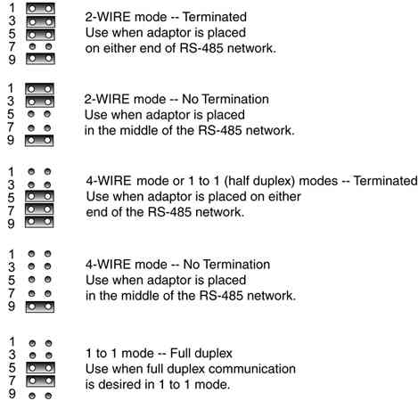
The Vesta RS-485 Adaptor has configurable termination and two-wire, four-wire and one-to-one modes. The modes are configured by jumpers as follows:
There are three modes supported by the Vesta RS 485 Adaptor. Each has its own system configuration and wiring requirements.
In this mode communications are half duplex, meaning that a given node can either be listening or talking at any given time. Only one node on the network can transmit at a time. The transmitting node broadcasts to all other nodes on the network.
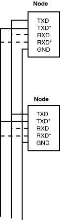
In two-wire mode all that is required is a cable connecting all grounds (pin 1), all TX pins (pin 2) and all TX* pins (pin 3).
The dotted lines connecting to each node are not part of the cabling. These connections are made by jumpers 1-2 and 3-4 on the RS-485 Adaptor.
Here, the node designated as the "master" always transmits to the other nodes on the network. All the other nodes, called "slaves," listen and transmit only to the master. Only half-duplex communication is supported in this mode.
The cabling for four-wire mode is a little more complex, as is shown in the following
figure. 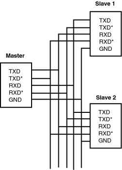
In this mode only two nodes exist on the RS-485 network. The TX pins on each node are connected to the corresponding RX pins on the other node.
Both full-duplex and half-duplex communications are supported. In order to use full duplex, install the jumpers as documented above and set the XMIT_ENABLE line permanently low. (Push-to-talk is described in the next section.)
In half-duplex mode, the node cannot listen and talk simultaneously. You must use XMIT_ENABLE to control the state of each node. See the next section for details on controlling XMIT_ENABLE.
All nodes are receivers unless enabled by software to transmit. This is sometimes called push-to-talk, or PTT. It is represented in the hardware by the XMIT_ENABLE line.
In one-to-one, full-duplex mode, RS-485 nodes are always enabled to transmit and receive. In this mode, assert PTT at the beginning of your program and leave it low for the duration of execution.
In all other modes, assert PTT before transmitting, then release PTT so that other nodes can transmit.
Check to make sure the hardware transmit buffer is empty before releasing PTT. Otherwise, the last one or two bytes of data will not transmit. (By executing a short delay loop before releasing PTT, you can be certain the XMIT buffer is empty.)
The push-to-talk line is controlled via calls to the function COMM, Mode 3. COMM (port #, 3, 1) asserts push to talk for the port. COMM (port #, 3,0) releases push to talk.
The amount of current drawn by an RS-485 Adaptor with outputs unloaded is 1 mA.
Dimensions are in inches.