Vesta SBC2000 controllers are equipped with the electronics to control alphanumeric Liquid Crystal Displays (LCDs).
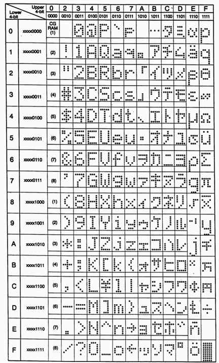
Pretty much all Character-based LCDs everywhere are based on the Hitachi HD44780 or equivalent controller IC. This chip has a built-in 192 character symbol set, plus 8 user-definable symbols, and can hold up to 80 characters in memory. Vesta Basic and Vesta C extensions have been written to provide easy control of this standard LCD command set.
Vesta sells several varieties of LCD, all using symbols made of 7 rows of 5 dots each and one extra row for the cursor.
All alphanumeric LCDs have the same connector pin out, and pass data in either 8bit or 4bit mode. Vesta SBC2000 LCD ports use 14 pin dual row headers. Some LCDs are equipped with single row headers, but the pin out is the same. Cabling any LCD to the SBC2000 is simply a matter of connecting pin 1 of the LCD to pin 1 of the LCD port and so on.
| Pin | Signal | Pin | Signal |
| 1 | Ground | 2 | +5 |
| 3 | Vo | 4 | RS |
| 5 | R/W* | 6 | EN |
| 7 | DB0 | 8 | DB1 |
| 9 | DB2 | 10 | DB3 |
| 11 | DB4 | 12 | DB5 |
| 13 | DB6 | 14 | DB7 |
Vesta LCD hardware uses the 4 bit mode configuration, so the SBC2000 interface does not use pins DB0-DB3. Data is transferred over data lines D7-D4. The 8-bit hex code is sent one nibble at a time, with the most significant nibble sent first. The function set in the initialization routine must accommodate this mode. See "Function Set" below.
Optional backlighting increases the visibility of LCDs. Power for LCD backlighting may be supplied through Pin 2 of the LCD connector (depending on whether or not the LCD itself allows this).
The LCD module has 2 registers; one for inputting instructions and one for writing data. Instructions are used to tell the module how and where to put the data.
The SBC2000 will initialize the LCD as follows:
| 0x28 | function set | DL=0 (4 bit), N=1 (2line), F=0 (5x7 font) |
| 0x0C | ON/OFF | D=1 (display on), C=0(cursor off), B=0 (no blink) |
| 0x06 | entry mode | I/D=1 (increment), S=0 (no shift on entry) |
| 0x01 | home |
PIPE & PRINT
One way to send text to the LCD is to use the Vesta Basic PRINT command. SBC2000-062 will send PRINT output to the LCD by default. With the rest of our SBCs you will need to use the PIPE command to direct PRINT commands to the LCD:
PIPE PRINT LCD
See PIPE.
LCD_Display( Text String )
The Vesta Basic LCD_Display function takes a text string as an argument and performs a series of "Write DD RAM" operations to send the text to the LCD.
The text will appear on the LCD display starting at the current cursor position, and move the cursor position to the position following the last character sent.
See LCD_COMMAND.
LCD_Command( Arg )
LCD_Command( Arg ) can be used to pass commands directly to the LCD module.
The Vesta Basic LCD_Command subroutine takes as an argument a number that corresponds to one of the LCD instructions provided by the module.
For example, LCD_Command(128) moves the cursor to the beginning of the first line.
See LCD_COMMAND, PIPE, and PRINT .
LCD Instruction Set
| Instruction Name | Arg | B7 | B6 | B5 | B4 | B3 | B2 | B1 | B0 |
| Clear Display | 1 | 0 | 0 | 0 | 0 | 0 | 0 | 0 | 1 |
| Return Home | 2-3 | 0 | 0 | 0 | 0 | 0 | 0 | 1 | * |
| Entry Mode | 1 4-7 | 0 | 0 | 0 | 0 | 0 | 1 | I/D | S |
| Display On/Off | 8-15 | 0 | 0 | 0 | 0 | 1 | D | C | B |
| Shift | 16-31 | 0 | 0 | 0 | 1 | S/C | R/L | * | * |
| Function Set | 32-63 | 0 | 0 | 1 | DL | N | F | * | * |
| Set CG RAM | 64-127 | 0 | 1 | CG RAM ADDRESS | |||||
| Set DD RAM | 128-255 | 1 | DD RAM ADDRESS | ||||||
| Write Data | Write Data | ||||||||
 Where:
I/D 1=increment    0=Decrement
S   1=Shift Display Window
    0=Shift Cursor
D   1=Display On   0=Display Off
C   1=Cursor On    0=Cursor Off
B   1=Blink On     0=Blink Off
S/C 1=Shift Display Window
    0=Shift Cursor
R/L 1=Shift to the Right
    0=Shift to the Left
DL  1=8 bit Mode   0=4 bit Mode
N   1=2 Lines      0=1 Line
F   1=10 Row Font  0=7 Row Font
When LCD_Command( Arg ) is issued in Vesta Basic with Arg=1, the controller sends the "Clear display" LCD instruction which writes hexadecimal code 20 (space) into all the DD RAM addresses and causes the cursor to return to Address 0 (ADD="80") and if the display has been shifted, returns it to the original position. In other words, any visible characters disappear and the cursor goes to the left edge of the display (on the first line on a 2 or 4 line LCD module.)
When LCD_Command( Arg ) is issued in Vesta Basic with Arg=2 or 3, the controller sends the "Return Home" LCD instruction which returns the cursor to the upper left corner, and if the display has been shifted, returns it to the original position. The DD RAM contents remain unchanged.
When LCD_Command( Arg ) is issued in Vesta Basic with Arg=4-7, the controller sends the "Entry Mode Set" LCD instruction which determines the how the display will behave when data is sent to the display.
| 4 | Cursor Left, No Text Move |
| 5 | Cursor & Text Move Left |
| 6 | Cursor Right, No Text Move |
| 7 | Cursor & Text Move Right |
When LCD_Command( Arg ) is issued in Vesta Basic with Arg=8-15, the controller sends the "Display On/Off" LCD instruction which controls whether the cursor or the displayed text above it are visible and whether they are blinking. The default setting is display on, cursor off, no blink, that is, the cursor position looks like ordinary text. Once an entry mode has been set it remains in force until another Entry Mode Set command is sent or until the system is restarted.
| 8-11 | Display Off | Cursor Off | Blink Off |
| 12 | Display On | Cursor Off | Blink Off |
| 13 | Display On | Cursor Off | Blink On |
| 14 | Display On | Cursor On | Blink Off |
| 15 | Display On | Cursor On | Blink On |
When LCD_Command( Arg ) is issued in Vesta Basic with Arg=16-31, the controller sends the "Shift" LCD instruction that causes the cursor position and (if specified) the text message to shift to the left or to the right.
| 16-19 | Cursor position | Left |
| 20-23 | Cursor position | Right |
| 24-27 | Text window | Left |
| 28-31 | Text window | Right |
When LCD_Command( Arg ) is issued in Vesta Basic with Arg=64-127, the controller sends the "Set CG RAM" LCD instruction which pushes the value in the CG RAM address (a binary number of AAAAAA) into the address counter. After this command, data will be written to from the CG RAM This is used for programming the Character Generator (CG) RAM.
See "CG RAM and Character Generation" below.
LCD_Command( Arg ) When LCD_Command( Arg ) is issued in Vesta Basic with Arg=128-255, the controller positions the cursor to the DD RAM position specified by LCD_Command( Arg ) when arg=128. After this command, data will be written to the DD RAM (display RAM).
When N=0 (1 line display), AAAAAAA is "00" to "47". (hexadecimal) When N=1 (2-line display), AAAAAAA for the first line is "00" to "27", and "40" to "67". (hexadecimal) for the second line. Because the MSB is set to "1", the hex codes are actually "80" to "A7", and "C0" to "E7" respectively.
See "DD RAM and Display Addressing" below.
There are two distinct areas of RAM within the LCD display module. The main area, called Display Data (DD) RAM, is dedicated to the display. CG or Character Generator RAM consists of 64 bytes ranging from 40 to 7F (hex). These 64 locations yield 8 "custom" 5x7 symbols.
DD RAM stores up to 80 characters. What appears on the screen is a "window" on the RAM. There may be two or more windows per line and there will also be some masked areas where the text data is stored but does not appear. The Shift Command, LCD_Command( 16-31 ), moves the data beneath the window so that different parts of the data are visible.
Address diagrams on the next page show RAM addresses as they appear after a Clear Display or Return Home instruction, or when an Entry Mode Set instruction is issued with S=0.
If a 2-line display has fewer than 40 characters per line, the cursor will advance off the screen after the last character of the first line. To put data on the second line, a Set DD RAM Address instruction must be sent.
When an Entry Mode Set instruction is issued with S=1, the display is shifted upon entry. This makes the characters look as though they are marching across the screen as they are entered. It also permits small displays (2x16s, for example) to have data stored in non-visible areas of DD RAM and shifted in to view with the Shift command. The last diagram shows how the address locations "wrap" in this mode.
Character Positioning
Vesta LCDs come in a variety of line configurations. Our most popular LCD has 4 lines that are each 20 characters long. Many other configurations are available from other manufacturers. If you are using non-Vesta LCDs you may need to consult the manual or just play around a little with sending text to discover the address for each position on your LCD. In general, the hexadecimal number 80 (represented in Vesta Basic as 0x80), points to the left-most character on the first line of the display.
The Vesta 2x8 LCD positions addresses in hexadecimal are as follows:
80 81 82 83 84 85 86 87

  C0 C1 C2 C3 C4 C5 C6 C7
LCD_Command(0x80)

  LCD_Display("*")
Will place an asterisk in the leftmost position of the first line.
On four line displays, the physical line 3 logically follows line 1, and line 4 follows line 2. When the cursor gets to the end of line 1, it will jump to line 3. Keeping track of cursor location for proper positioning is important.
80 81 82 83 84 85 86 87 88 89 8A 8B 8C 8D 8E 8F 90 91 92 93

  C0 C1 C2 C3 C4 C5 C6 C7 C8 C9 CA CB CC CD CE CF D0 D1 D2 D3

  94 95 96 97 98 99 9A 9B 9C 9D 9E 9F A0 A1 A2 A3 A4 A5 A6 A7

  D4 D5 D6 D7 D8 D9 DA DB DC DD DE DF E0 E1 E2 E3 E4 E5 E6 E7
Line 1
C0 C1 C2 C3 C4 C5 C6 C7 C8 C9 CA CB CC CD CE CF D0 D1 D2 D3

  D4 D5 D6 D7 D8 D9 DA DB DC DD DE DF E0 E1 E2 E3 E4 E5 E6 E7
Line 2
80 81 82 83 84 85 86 87 88 89 8A 8B 8C 8D 8E 8F 90 91 92 93

  94 95 96 97 98 99 9A 9B 9C 9D 9E 9F A0 A1 A2 A3 A4 A5 A6 A7
Character Generator (CG) RAM is a useful accessory. CG RAM allows the creation of up to 8 special 5x7 dot characters or symbols. Once programmed, the newly formed characters may be accessed as if they were in the normal ROM font set. This ROM contains 192 unchangeable characters. Thus the CG RAM expands the character representation available to the user up to 200 symbols.
Note: This is RAM, and must be reprogrammed if display power is interrupted. If used regularly, programming can be made part of the initialization routine.
CG Ram does not have to be used or attended to during normal display operation.
CG RAM byte is 8 bits wide, but only the 5 least significant bits appear on the LCD. Thus D4 represents the left-most dot and D0 the right-most dot. To illustrate, loading a CG RAM byte with 1F turns all dots in that row on; loading a byte with 00 turns all dots off. All 7 or 8 rows must be programmed at each desired CG location.
The programming procedure is:
This procedure may be continued until all CG bytes have been loaded.
The CG RAM can be used to create an attractive, "reverse-video" 3x5 pattern. Numerals look especially good in this format. Most letters can be executed. The limitation of 8 characters can be circumvented by creating a "library" of custom symbols, each totaling 8, resident in the host system. Eight custom symbols can be displayed at any ONE time.
The CG RAM can be periodically reloaded as display requirements change. If you reload a CG location that is currently on the display, the change will be immediately apparent.