The BADC12 attaches to the V104 bus, and provides two 8-channel, bipolar, dual-range analog to digital converters. Its software can be configured for +4v, +2v, +/-4v, +/-2v.
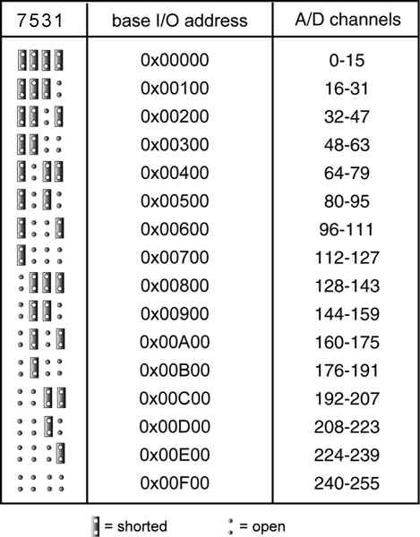
1. Install ADDR jumpers to pins A8, A9, A10 and A11 (as shipped).
2. Connect the BADC12 cable to the SBC2000.
3. Execute the following code:
GLOBAL channel AS INTEGER
CONSTANT crlf AS STRING = "\013\010"

AIN_CONFIG(0, 10)
REM Read all 16 ADC channels
DO
   FOR channel = 0 TO 15
      PRINT crlf, channel, ": ", AIN(channel)
   NEXT channel
LOOP UNTIL 0
AIN_CONFIG() configures extensions for running analog to digital conversions. Func determines which parameter is being configured. Value sets up the parameter selected by function. When the BADC12 is selected using func=0, the rest of the conversion parameters are automatically set to a default configuration.
| Func | Setting | Value | Configuration |
| 0 | Select Peripheral | 10 | Selects BADC12 |
| 2 | Polarity | 0 | Unipolar (default) |
| 1 | Bipolar | ||
| 3 | Range | 0 | Limited to Vref (4V) (default) |
| 1 | Limited to Vref/2 (2V) | ||
| 4 | Powerdown mode | 0 | Full Powerdown |
| 1 | Standby Powerdown | ||
| 2 | Normal (default) |
Powerdown mode: At the end of each command byte, the ADC is told to which powerdown mode to enter.
Full powerdown: Consumes almost no current but takes 200ms for the chip to return to operations.
Standby powerdown: Consumes more current and wakes quicker. The ADC chip must be fully powered to run a conversion or the results will be incorrect.
The BADC12 peripheral supports interrupt-driven conversions. To use the interrupt lines, make sure that jumper ADDR pin 9-10 is in place. This provides a pull-up for the open collector-interrupt outputs on each of the ADC chips. The BADC12 interrupt line is connected to the BUS INT line, J1B-6.
| Pin | Signal | Pin | Signal |
| J1A-1 | N.C. | J1B-1 | GND |
| J1A-2 | D7 | J1B-2 | N.C. |
| J1A-3 | D6 | J1B-3 | +5V |
| J1A-4 | D5 | J1B-4 | N.C. |
| J1A-5 | D4 | J1B-5 | N.C. |
| J1A-6 | D3 | J1B-6 | INT* |
| J1A-7 | D2 | J1B-7 | N.C. |
| J1A-8 | D1 | J1B-8 | N.C. |
| J1A-9 | D0 | J1B-9 | N.C. |
| J1A-10 | N.C. | J1B-10 | GND |
| J1A-11 | AEN | J1B-11 | N.C. |
| J1A-12 | A19 | J1B-12 | N.C. |
| J1A-13 | A18 | J1B-13 | IOW |
| J1A-14 | A17 | J1B-14 | IOR |
| J1A-15 | A16 | J1B-15 | N.C. |
| J1A-16 | A15 | J1B-16 | N.C. |
| J1A-17 | A14 | J1B-17 | N.C. |
| J1A-18 | A13 | J1B-18 | N.C. |
| J1A-19 | A12 | J1B-19 | N.C. |
| J1A-20 | A11 | J1B-20 | N.C. |
| J1A-21 | A10 | J1B-21 | N.C |
| J1A-22 | A9 | J1B-22 | N.C |
| J1A-23 | A8 | J1B-23 | N.C. |
| J1A-24 | A7 | J1B-24 | IRQ4 |
| J1A-25 | A6 | J1B-25 | IRQ3 |
| J1A-26 | A5 | J1B-26 | N.C. |
| J1A-27 | A4 | J1B-27 | N.C. |
| J1A-28 | N.C. | J1B-28 | ALE |
| J1A-29 | A2 | J1B-29 | +5V |
| J1A-30 | A1 | J1B-30 | N.C. |
| J1A-31 | A0 | J1B-31 | N.C. |
| J1A-32 | GND | J1B-32 | GND |
| Pin | AIN0-7 Signal | AIN8-15 Signal |
| 1 | AGND | AGND |
| 2 | AGND | AGND |
| 3 | AIN0 | AIN8 |
| 4 | AIN1 | AIN9 |
| 5 | AIN2 | AIN10 |
| 6 | AIN3 | AIN11 |
| 7 | AIN4 | AIN12 |
| 8 | AIN5 | AIN13 |
| 9 | AIN6 | AIN14 |
| 10 | AIN7 | AIN15 |
The amount of current drawn by a BADC12 is 70 mA.
Dimensions are in inches.